Gathering networks: the backbone of upstream energy distribution
Pipelines that form gathering networks are an important aspect of upstream energy distribution. They are used to transport crude oil or natural gas from production site facilities to a central collection point for further distribution.
Gathering networks are different from midstream pipelines since they operate at lower pressures and flows and are also smaller in diameter. They are a lot more transient in their behavior, which has a direct effect on tuning of a leak detection system. In addition, each well behaves differently, being switched on or off multiple times per day and injecting at different flow rates. This can make optimizing a leak detection system challenging.
Since gathering networks are often located in high consequence areas (HCAs) and remote locations, leak detection is a vital requirement. They are often multiphase, carrying oil, water and gas to the stations before separation. It’s crucial that the leak detection technology implemented on a gathering network is able to detect leaks for varying product mix in the pipeline.
In this blog, Sales and Support Engineer Angela Maya for Atmos in Latin America covers the following areas relating to leak detection on gathering networks:
- Challenges faced by leak detection systems on gathering networks
- Factors that can influence the performance of leak detection systems
- Volume balance and negative pressure wave methods vs the real time transient model (RTTM)
- Examples of leading leak detection systems overcoming the challenges presented by gathering networks
- Leak detection use cases from gathering network projects
- Core considerations for a leak detection system on gathering networks
Challenges faced by leak detection systems on gathering networks
There are various key challenges faced by leak detection systems on gathering networks, including:
- Product composition is variable, depending on the specific well, production field and region
- Density measurements are usually not available to the supervisory control and data acquisition (SCADA) system
- Gathering networks can have many injections and deliveries
- Well-pads can be added weekly as new production comes online
- The dynamic nature of injecting from numerous wells at different flow rates
- Access is limited to the right of ways for adding instrumentation at the branch connections. There is typically only flow and pressure data available from the custody transfer units at the wells and at the outlets
- Constrained communications bandwidth limits the SCADA update rate to minutes, at best
- Draining can cause slack in the network, pipelines filling as injection pumps operate intermittently1
Factors that can influence the performance of leak detection systems
- The number and quality of sensors on the pipeline
- Availability and quality of the telecommunications system
- Pipeline operating scenarios, such as transient events from continuous start and stop of injections and deliveries and slack flow conditions1
The leak detection system implemented needs to be able to overcome these core challenges and factors that influence performance to make it reliable.
Volume balance and negative pressure wave methods vs the real time transient model (RTTM)
There are four key factors that need to be considered when selecting a leak detection system:
- High sensitivity so that it detects small leaks
- Short response time to alarm
- High leak location accuracy
- Low false alarm rate
Both the volume balance and real time transient model (RTTM) successfully detect leaks during transient conditions, which occur regularly in gathering networks. The RTTM method needs to raise the minimum detectable leak size threshold during transient operations to reduce false leak alarms and may require additional instrumentation.1 This arguably makes it less reliable and more costly than a leak detection system that uses volume balance.
The RTTM method calculates the real time profiles for flow, pressure and density (or temperature) along the pipeline.2 The model monitors the discrepancy between the measured and calculated values potentially caused by a leak.3
A statistical volume balance (SVB) is a method for leak detection where it’s used in the corrected volume balance of the pipeline in conjunction with the statistical approach to determine if there’s a leak or not3. Leak detection systems like Atmos Pipe use the statistical corrected volume balance (SCVB), the first of its kind released in 1995.
The SCVB has been successfully deployed on numerous gathering networks and is a popular method used in the new shale boom pipelines.1 Where the RTTM and sole volume balance methods rely on accuracy, SCVB relies on the repeatability of the measurements, which makes it a better choice for instrumentation requirements and scan rate. In addition, SCVB achieves good reliability and sensitivity, even if the existing instrumentation is of limited accuracy, while upgrading instrumentation accurate enough to support an RTTM method on gathering networks can incur a high CAPEX to upgrade. In addition tuning of an RTTM as new wells are introduced can be time-consuming and costly.
Negative pressure wave methods use pressure transmitters, but they should be bound to each branch and adding this intermediate instrumentation to gathering networks can be difficult.1 Overall, negative pressure wave methods can provide very sensitive leak detection with a response time that is faster than both RTTM and SCVB.1 Technology like Atmos Wave is sophisticated and effective on multiphase pipelines. Unlike other methods, technologies that use negative pressure wave are not limited by the liquid or gas mixture. Multiphase flow is hard to measure and is in many cases not possible and when it is measured it has low accuracy and repeatability. This makes negative pressure wave the only feasible leak detection system as it works even if no accurate flow measurement is available.
Examples of leading leak detection systems overcoming the challenges presented by gathering networks
Technology like Atmos Pipe and Atmos Wave are ideal for use on gathering networks. They encompass all four key factors that need to be considered when selecting a leak detection system but also help overcome the core challenges associated with gathering networks.
Atmos Pipe
Atmos Pipe is a field proven technology of over 25 years. The software uses flow and pressure data from SCADA and other control systems to detect and locate leaks.
It’s suitable for single-phase gathering lines because it can detect leaks under all operating conditions and there’s no change in the minimum leak size during transients. The leak detection system can also minimize the effect of fluid property changes, supply and demand variations and instrument faults including telecommunication failures.
View the product Download the brochure
Atmos Wave
Atmos Wave uses negative pressure waves to detect a leak using fast response pressure meters. The comprehensive algorithms filter process noise and interference from the pressure data to create a detailed 3-dimensional map. With this pipeline operators can quickly and clearly differentiate true leak or theft events from pressure changes caused by transient operations and declare loss of containment quickly and reliably.
View the product Download the brochure
Hardware
It’s suitable for single-phase gathering lines because it can detect leaks under all operating conditions and there’s no change in the minimum leak size during transients. The leak detection system can also minimize the effect of fluid property changes, supply and demand variations and instrument faults including telecommunication failures.
Vioew Atmos AWAS units Read the data sheets
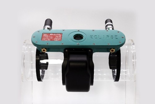
Figure 1: Atmos Eclipse fitted to a model pipeline
Its clamp-on design also makes Atmos Eclipse very easy and quick to install for rapid deployments. Multiple communications options including TCP/IP, line of sight radio, GSM (3/4G) and Modbus mean that data is always transmitted back to the pipeline controllers in real-time. This overcomes the bandwidth limitations usually associated with gathering lines where a SCADA system can often take minutes at best to update.
AWAS data acquisition units can also be used with Atmos Wave to overcome communications issues. The central data storage capability means that up to 4.5 hours’ worth of data can be stored to ensure nothing is lost if there is a communications outage.

Figure 2: Atmos’ range of three channel, high-speed, high-resolution, pressure data acquisition units (AWAS 3, 4, 6, 6G and 7)
View Atmos AWAS units Read the data sheets
Leak detection use cases from gathering network projects
Since gathering networks are upstream and closely linked to the drilling process, they present several difficult scenarios. In addition to all the challenges previously mentioned, the leak detection system needs to be able to handle the introduction of new inlets into the system, which causes a very dynamic pipeline layout.
To successfully implement a leak detection system on gathering networks there’s a clear process that needs to be followed. At Atmos International (Atmos), there’s an information gathering phase where the network is analyzed for the schematics of the pipeline. A remote connection is established to the leak detection system server and the system is then implemented onsite and subsequently commissioned.
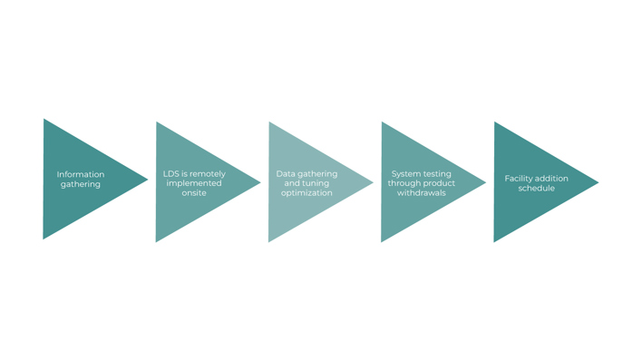
Figure 3: Process for implementing a leak detection system on gathering lines
Following this, Atmos engineers will commence tuning to optimize the system. System testing is carried out by conducting controlled fluid withdrawals to prove the leak detection system functionality. The facility addition schedule is planned carefully to meet installation and maintenance requirements going forwards.
Atmos leak detection systems are flexible so that engineers can include new additions easily to meet the needs of the client. This would not be the case for RTTM systems where the hydraulic model needs to be configured and tuned each time a new addition is required.
It’s important that the leak detection system is flexible and easy to tune. On one project Atmos completed, five facilities were added in one week thereafter more and more were added as the project progressed. Initially, it was agreed that 24 segments would be included, however in total a further 75 were added, resulting in a total of 99 segments.
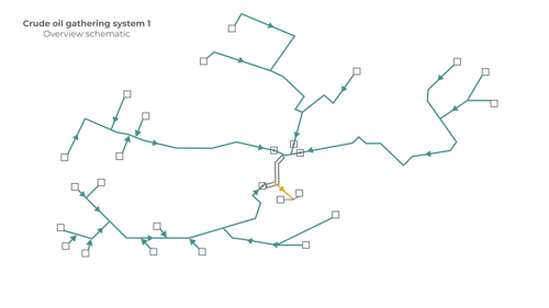
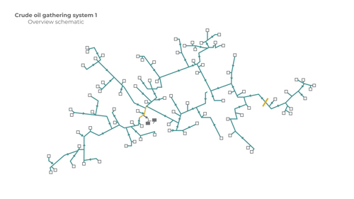
Figure 4: Gathering network with new facilities added
The flow rate of the gathering lines has more than doubled since the completion of the initial project. The leak detection system was able to maintain a 1.5% minimum leak size (or better), demonstrating how it can adapt to the changing requirements of gathering networks.
Core considerations for a leak detection system on gathering networks
Since gathering networks differ greatly from midstream pipelines, it’s essential to take a few areas into consideration. This is because networks present very specific challenges.
It’s crucial to consider the type of method the leak detection system uses. The RTTM method is evidently less suitable for gathering networks due to its instrumentation requirements, complexity and scan rate. There could also be CAPEX requirements to upgrade the network instrumentation to be able to maintain the RTTM system. The SCVB and negative pressure wave methods are more reliable. In addition, options like Atmos Wave Flow use the multi-method approach to help reduce uncertainty.
Hardware can also be used as part of a leak detection strategy for gathering networks. In areas where there are limited communications for example, a unit like Atmos Eclipse can be used to access key data on the pipeline in real-time.
The flexibility of the leak detection system to expand as the gathering network grows is also important. For the sensitivity to be maintained, it needs to work with the facility adding schedule. As explained above a gathering network can quickly go from 24 to 99 facilities. With this, it’s also crucial to consider the process of implementation that the provider undertakes.
References
2 https://saudijournals.com/media/articles/SJEAT-1237-48.pdf
3 https://pipelinepodcastnetwork.com/episode-24-rttm-leak-detection-giancarlo-milano/